

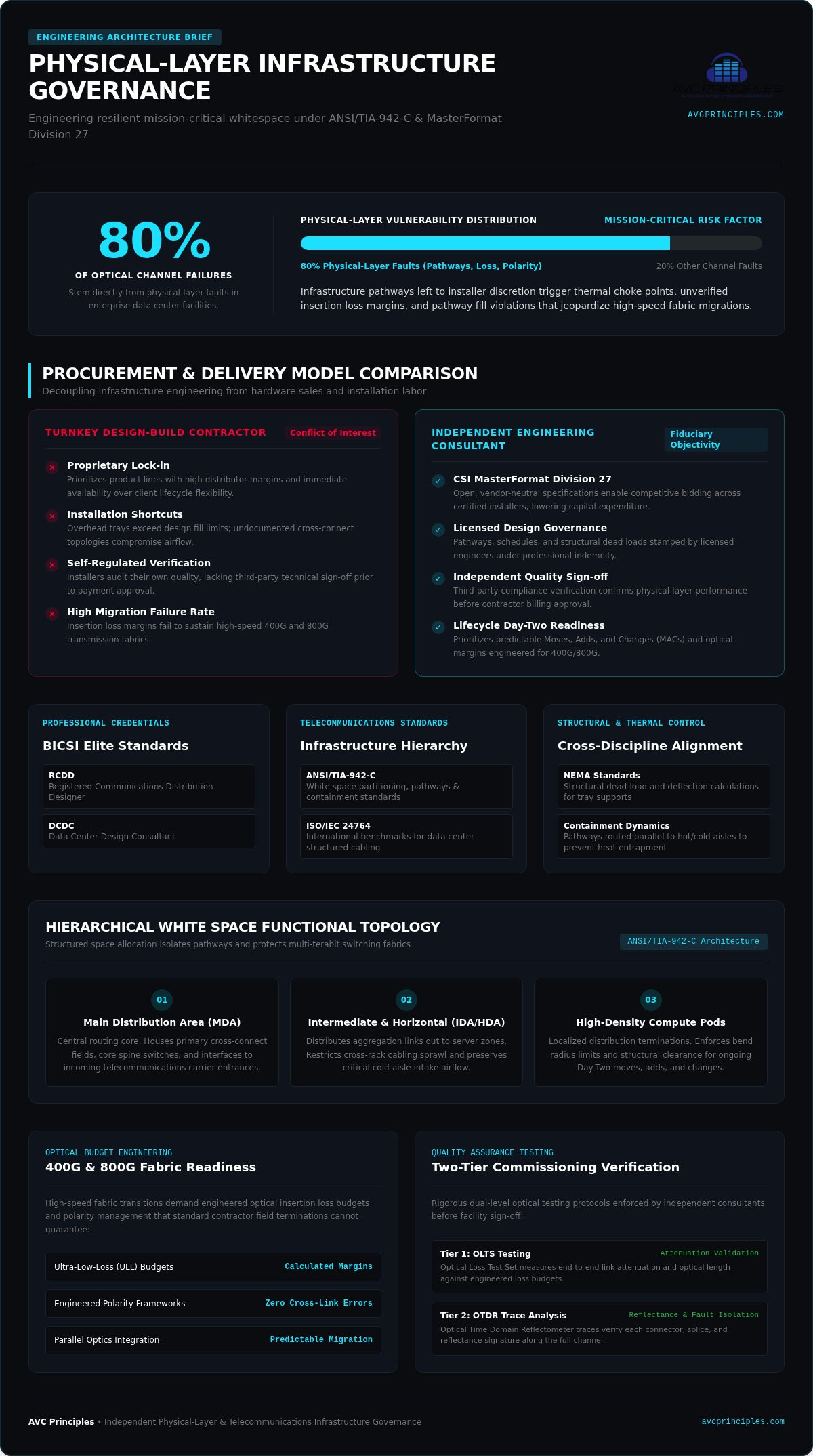
Up to 80 percent of optical channel failures in enterprise facilities stem directly from physical-layer faults, yet infrastructure pathways are often left to contractor discretion. Engaging independent data center cabling design consultants eliminates this structural vulnerability before procurement begins. Independent engineering prevents vendor lock-in, mitigates operational downtime, and secures physical network longevity across the entire facility lifecycle.
You've likely seen the fallout of proprietary design shortcuts: thermal choke points behind overhead trays exceeding standard design fill limits, undocumented cross-connect topologies, and insertion loss margins that fail high-speed 400G and 800G fabric migration. Independent consulting protects your capital expenditure through vendor-neutral CSI MasterFormat specifications, predictable Day-Two pathway scalability, and verified optical performance metrics. This technical guide examines the engineering standards, pathway calculations, and ANSI/TIA-942-C validation protocols required to deliver resilient, mission-critical physical layer architecture.
Key Takeaways
- Discover how independent data center cabling design consultants develop open Division 27 specifications that eliminate proprietary vendor lock-in and protect procurement capital.
- Master pathway sizing and structural dead-load calculations to maintain strict compliance with cable tray fill envelopes and preserve critical containment airflow.
- Formulate ultra-low-loss optical insertion budgets and engineered polarity frameworks to guarantee transmission integrity across 400G and 800G fabrics.
- Deploy hierarchical white space distribution topologies that isolate physical pathways to ensure predictable Day-Two operational expansion and prevent rack-level congestion.
- Establish rigorous Tier 1 OLTS attenuation and Tier 2 OTDR trace commissioning protocols to validate physical-layer compliance before facility sign-off.
The Role of Independent Data Center Cabling Design Consultants
Mission-critical uptime begins at the physical layer. Contracting firms often market "turnkey design-build" services, bundling pathway layout into physical installation labor. This practice introduces an immediate structural conflict of interest. Installers prioritize product lines with high distribution margins, ease of installation, and immediate distributor availability over client lifecycle flexibility. Independent data center cabling design consultants solve this problem by decoupling infrastructure governance from hardware sales and installation labor.
Consulting engagements enforce absolute fiduciary objectivity. Independent engineering consultants deliver vendor-neutral architectural drawings, comprehensive MasterFormat Division 27 procurement specifications, and performance verification standards. By operating independently from component manufacturers and installation trades, these specialists eliminate proprietary vendor lock-in. Open competitive bidding on equivalent physical layer systems lowers procurement overhead while securing structural longevity.
Independent Engineering Consulting Versus Design-Build Contracting
Design-build contractors frequently rely on single-source manufacturer alignments that constrain future expansion. Independent engineering models, by contrast, utilize structured design-bid-build workflows:
- Design governance: Physical pathways, rack distributions, and cable schedules are designed and stamped by licensed engineers, ensuring strict professional indemnity.
- Competitive procurement: Master specifications establish open physical and optical parameters, allowing multiple certified installers to submit transparent bids.
- Lifecycle flexibility: Architectural layouts prioritize Day-Two moves, adds, and changes (MACs) rather than convenient cable routing during initial builds.
- Quality verification: Consultants perform third-party sign-off, confirming compliance before approving contractor billing.
Core Competencies and Professional Certifications
Physical telecommunications engineering demands deep multi-disciplinary fluency. Qualified data center cabling design consultants maintain elite industry credentials, notably the BICSI Registered Communications Distribution Designer (RCDD) and Data Center Design Consultant (DCDC) designations. These certifications ensure adherence to the ANSI/TIA-942 telecommunications infrastructure standard and ISO/IEC 24764 benchmarks, governing physical hierarchy across Main, Intermediate, and Horizontal Distribution Areas.
True consultants coordinate across architectural disciplines. Structural deflection limits under NEMA standards determine pathway supports. Mechanical cooling models dictate tray positioning to prevent airflow impedance within hot and cold containment aisles. Independent consultants align structural dead loads, optical transmission limits, and thermal boundaries into a singular, cohesive physical layer architecture.
Architectural Frameworks and Physical Topology Design
High-density processing clusters reshape physical whitespace requirements. Without strict topological segmentation, cabling pathways rapidly degenerate into unmanageable congestion points that restrict airflow and violate bend radii. Professional data center cabling design consultants establish rigid physical boundaries that separate backbone transport from localized distribution. This structural division ensures that multi-terabit switching fabrics expand smoothly without interrupting operational compute hardware.
Consultants model pathways around thermal boundaries. Overhead wire mesh trays and solid ladder racks must route parallel to hot and cold aisle containment systems rather than crossing perpendicular to exhaust plumes. Calculating spatial footprints early prevents cabling density from restricting cold air intake or trapping heat across high-density cabinets.
Functional Space Allocation Under ANSI/TIA-942-C
The structured layout begins with clear zoning defined by current TIA-942 engineering and cabling specifications. Modern white space design partitions infrastructure into distinct functional spaces:
- Main Distribution Area (MDA): The central routing core. Houses primary cross-connect fields, core spine switches, and interfaces to incoming telecommunications carrier entrance facilities.
- Horizontal Distribution Area (HDA): Intermediate distribution fields serving dedicated server cabinet rows. HDAs transition high-fiber-count backbone trunks into localized leaf connectivity. Under ANSI/TIA-942-C, cabinets deployed within MDAs and HDAs must maintain a minimum width of 800 mm (31.5 inches) to accommodate vertical slack managers and optical containment.
- Equipment Distribution Area (EDA): Rack spaces dedicated strictly to compute nodes, storage arrays, and point-of-load hardware terminations.
Top-of-Rack, End-of-Row, and Centralized Switching Architectures
Selecting an equipment switching topology directly impacts pathway capacity. Top-of-Rack (ToR) configurations place leaf switches directly within each compute cabinet. This limits horizontal copper lengths to short inter-rack jumps, but it dramatically increases cabinet-level power consumption, maintenance touchpoints, and unutilized switch port counts. Conversely, End-of-Row (EoR) and Middle-of-Row (MoR) architectures aggregate network hardware into centralized switching bays, dramatically reducing overall active ports at the expense of high-volume horizontal cabling pathways.
Independent engineering firms mitigate these structural trade-offs through centralized structured cross-connects. Interposing passive patch fields between core switching fabrics and server cabinets isolates permanent backbone cabling from operational equipment churn. Server administrators execute MACs entirely within passive fields. Active transceiver optics and backbone trunk links remain undisturbed. Organizations evaluating large-scale physical layer upgrades can review AVC Principles ICT Infrastructure Design to evaluate vendor-neutral pathway architectures tailored to their computational profiles.
High-Density Fiber and Copper Engineering Specifications
Optical link engineering leaves no room for guesswork. Multi-terabit spine-and-leaf fabrics rely on PAM4 signaling, cutting optical power loss margins to thin thresholds. Standard factory-grade terminations often introduce unacceptable attenuation. Independent data center cabling design consultants perform granular link-loss calculations to verify that planned optical channels support active optics across multiple generations of switching hardware.
Copper media selection demands equal precision. While passive direct-attach copper handles short-reach intra-rack jumps, signal loss at high Nyquist frequencies restricts its viability beyond two meters. Consultants specify Category 6A F/UTP or S/FTP shielded twisted-pair cabling for out-of-band server management and environmental sensor networks. Shielded copper suppresses alien crosstalk and maintains 10GBASE-T performance across the full 100-meter channel.
Optical Media Selection and Insertion Loss Engineering
Single-mode OS2 fiber remains the gold standard for high-bandwidth backbones. Formulating specifications around IEEE standards for high-speed data center physical layers requires strict insertion loss budgeting:
- 400GBASE-DR4 / 800GBASE-DR8: IEEE limits total channel attenuation to 3.0 dB across a 500-meter reach. A standard ANSI/TIA-568 MPO mated pair permits 0.75 dB loss. Deploying four mated pairs immediately consumes the entire budget before factoring in fiber attenuation.
- Ultra-Low-Loss (ULL) assemblies: Consultants mandate ULL MPO connectors rated at ≤ 0.35 dB per mated pair. This preserves sufficient headroom for cross-connect bulkheads.
- Multimode constraints: Short-reach multimode optics (OM4/OM5) cap channel insertion loss at 1.8 to 1.9 dB over 100 meters, leaving almost zero margin for intermediate patching.
MPO/MTP Array Connectors and Polarity Governance
High-density parallel optics require disciplined array connectivity. Qualified data center cabling design consultants specify pre-terminated Base-8, Base-16, or Base-24 MPO trunking to align with 400G and 800G transceiver architectures. Base-8 configurations match 4-lane transmit and receive optics (such as 400G DR4) without leaving unutilized dark fibers inside expensive trunk assemblies.
Polarity governance prevents severe deployment delays. Engineering documents explicitly define TIA-568 Method A, Method B, or Method C polarity across all pre-terminated trunks, cassettes, and patch cords. Clear architectural drawings eliminate field technician confusion, preventing unauthorized cable manipulation or pin swapping in live white space environments. Independent consultants also mandate Angled Physical Contact (APC) 8-degree ferrule geometry across all single-mode MPO terminations. This polish delivers Optical Return Loss (ORL) performance exceeding -35 dB, shielding high-baud PAM4 lasers from damaging back-reflection.
Cabling Pathway, Containment, and Structural Load Calculations
Overhead pathways support massive dead weight while traversing critical airflow corridors. High-density Category 6A copper runs generate physical dead loads ranging between 40 and 65 pounds per linear foot. Independent data center cabling design consultants engineer raceway infrastructures to prevent catastrophic tray deflection, mechanical jacket compression, and thermal choke points across server rows.
Pathway engineering also protects signal integrity from power distribution infrastructure. Routing sensitive optical trunks and twisted-pair cabling directly beside high-ampacity overhead busways introduces severe coupled electromagnetic interference (EMI). Consultants calculate clear physical separation boundaries, enforcing dedicated pathway elevations that isolate telecommunications raceways from electrical runs, wet pipe fire suppression lines, and fluid supply lines.
Pathway Sizing and Tray Loading Calculation Protocols
Raceway sizing balances physical volume against mechanical stress. Independent consultants calculate cross-sectional fills according to strict regulatory and engineering criteria:
- Design fill envelope: NFPA 70 (NEC Article 392) limits cable fill within ladder and ventilated trough trays to a maximum of 50 percent cross-sectional area. Engineering specifications enforce an initial baseline cap of 40 percent per ANSI/TIA-569-E, reserving vital capacity for Day-Two MAC operations.
- Support span calculations: Heavy cabling tiers demand rigorous trapeze hanger spacing. Design specifications require trapeze supports every four to five feet, using heavy-duty unistrut channels and 1/2-inch threaded rod assemblies calculated to meet NEMA VE 1 and VE 2 load classes (such as Class 12C or 20C).
- Bundle geometry: Engineering drawings restrict bundle diameters to 24 or 48 cables, eliminating bottom-tier crush injuries and maintaining heat dissipation across PoE runs.
Thermal Management and Firestop Compartmentalization
Pathway geometry dictates data center aerodynamics. Legacy underfloor installations frequently create "cable dams" that disrupt static plenum pressure and starve perforated floor tiles. Modern standards route high-density distribution overhead, elevating pathways clear of hot-aisle containment exhausts and direct-to-chip liquid cooling manifolds per ANSI/BICSI 002-2024 recommendations.
Pathway penetrations through fire-rated perimeter walls require certified containment. Consulting engineers reject manual putty packing in favor of pre-engineered, modular firestop sleeves tested under ASTM E814 and UL 1479 standards. These systems feature internal intumescent elastomer mechanisms that expand under heat while permitting zero-maintenance cable pulls. Before executing pathway procurement, infrastructure managers should engage AVC Principles for ICT Infrastructure Design to validate structural loading capacities and thermal pathway envelopes.
Engineering Documentation, Procurement, and Quality Commissioning
Unambiguous engineering documentation controls procurement outcomes. When physical layer requirements lack granular definitions, installation contractors fill the vacuum with proprietary substitutions and field improvisation. Independent data center cabling design consultants protect client capital by delivering complete Division 27 contract documents. These deliverables transform conceptual network architectures into legally binding procurement packages.
End-to-end design documentation bridges schematic intent and final handover. By generating coordinated BIM models at LOD 300 to LOD 400 alongside detailed AutoCAD schematics, consultants eliminate pathway clashes before raceways hang from structural steel. Comprehensive cable schedule matrices define source, destination, media type, and connector pinning for every link in the facility.
Division 27 Technical Specification Architecture
MasterFormat Section 27 10 00 establishes non-negotiable performance criteria for structured telecommunications packages. Independent consultants construct specifications that eliminate contractor-driven brand monopolies:
- Material baselines: Specifications dictate physical, optical, and mechanical performance thresholds across cable assemblies, patch panels, and pathway hardware without specifying single-source proprietary part numbers.
- Submittal governance: Contractors must submit third-party laboratory verification, factory test reports, and physical samples before procuring components.
- Equivalency clauses: Technical criteria define acceptable alternative manufacturers, ensuring multi-vendor competition during bid phases while preventing downgrades in component quality.
Commissioning Verification and Field Testing Oversight
Installation quality requires empirical proof. Experienced data center cabling design consultants specify comprehensive quality assurance matrices that prevent contractors from self-certifying their work. Specifications mandate factory-calibrated field testers configured to record raw, unedited electronic data files rather than static, easily manipulated PDF summaries.
Commissioning protocols enforce two-tier optical verification. Tier 1 testing uses an Optical Loss Test Set (OLTS) to measure absolute channel attenuation and link length against engineered loss budgets. Tier 2 testing requires Optical Time Domain Reflectometer (OTDR) trace analysis on all single-mode trunks to verify individual splice losses, mated connector attenuation, and reflectance compliance. Finally, consultants audit physical labeling schemes against ANSI/TIA-606-C standards, confirming that rack designations, patch fields, and distribution cables match the digital twin database exactly. Facility owners can engage AVC Principles for independent engineering consulting and ICT infrastructure design oversight across their mission-critical deployments.
Engineering Resilient Physical Layer Infrastructure
High-speed computational environments cannot rely on ad-hoc physical layer implementations. Mitigating transmission faults across dense switching fabrics requires exact optical attenuation modeling, verified return loss margins, and strict pathway fill disciplines. Engaging independent data center cabling design consultants guarantees that structural pathways, thermal envelopes, and passive distribution topologies operate as an integrated system, protecting your facility against costly retrofits and unexpected downtime.
Fiduciary independence transforms capital deployment. Objective Division 27 specifications protect your budget by driving open competitive bidding and eliminating proprietary contractor markups. Paired with rigorous two-tier testing matrices, independent oversight verifies that every installed permanent link meets its calculated performance ceiling before active compute loads go live.
Ready to secure your physical network architecture? Consult with the engineering specialists at AVC Principles for expert ICT Infrastructure Design to develop comprehensive, vendor-neutral specifications and end-to-end design documentation tailored to your enterprise facility.
Frequently Asked Questions
What is the primary difference between a cabling consultant and a cabling contractor?
A cabling consultant provides vendor-neutral design engineering, technical specifications, and performance oversight without selling hardware or installation labor. A contractor sells physical labor and equipment to build the layout. Independent data center cabling design consultants work directly for the facility owner under professional indemnity, ensuring design integrity and open competitive bidding. Contractors focus on installation speed and material margins, which can introduce proprietary lock-in.
Why is an independent cabling design consultant necessary for data center projects?
Independent consultants eliminate conflicts of interest inherent in design-build contractor models. They protect procurement budgets by authoring open, competitive Division 27 specifications instead of closed, single-source bills of materials. Independent data center cabling design consultants coordinate pathways directly with structural engineers and mechanical teams, ensuring raceways don't disrupt cooling airflow, exceed tray weight ratings, or compromise long-term operational scalability during Day-Two changes.
What design standards govern enterprise data center cabling architecture?
Data center cabling architecture follows ANSI/TIA-942-C for infrastructure resiliency tiers and distribution zoning across Main, Intermediate, and Horizontal distribution spaces. Additional core benchmarks include ANSI/BICSI 002-2024 for data center design best practices, ISO/IEC 24764 for international white space cabling, and NFPA 70 (NEC Article 392) for raceway fill capacities. Optical and electrical transmission limits adhere to IEEE 802.3 Ethernet standards governing 400G and 800G fabric links.
How do cabling design consultants calculate optical insertion loss budgets?
Optical loss calculations aggregate baseline fiber attenuation, connector mating losses, and splice penalties across the permanent link. Engineers determine maximum tolerable attenuation from IEEE 802.3 transceiver specifications, such as 3.0 dB for 400GBASE-DR4 links over single-mode fiber. Consultants deduct 0.35 dB for each ultra-low-loss MPO interface and 0.1 dB per fusion splice, reserving an engineered margin of at least 30 percent for aging transceivers and future patching additions.
What is included in a Division 27 structured cabling specification package?
A complete MasterFormat Division 27 package contains detailed CSI three-part written specifications (27 10 00 and sub-sections), technical equipment schedules, and CAD/BIM floor plans. Deliverables include pathway routing layouts, cabinet elevation diagrams, and exact rack cross-connect topologies. The package also establishes binding contractor submittal requirements, vendor-neutral material equivalency rules, labeling criteria matching ANSI/TIA-606-C, and mandatory Tier 1 OLTS and Tier 2 OTDR field commissioning procedures.
How do consultants address high-density fiber requirements for modern compute fabrics?
Consultants specify single-mode OS2 backbones utilizing pre-terminated Base-8 or Base-16 MPO trunk assemblies. This aligns connector lanes directly with parallel optic transceivers without wasting internal fiber cores. They also integrate Very Small Form Factor (VSFF) duplex connectors to triple front-panel patch density. Precise polarity schemes (such as TIA-568 Method B) and Angled Physical Contact (APC) finishes are mandated to prevent back-reflection and maintain optical return loss above -35 dB.
When should an enterprise engage a data center cabling design consultant during a project?
Enterprise teams should engage consultants during the schematic design phase before architectural spatial layouts and structural grids finalize. Early involvement ensures that overhead pathway elevations coordinate with mechanical containment ducting, high-density power busways, and structural trapeze drop points. Engaging consultants early prevents expensive structural revisions, eliminates contractor redesign fees, and ensures procurement packages hit the market with fully defined, vendor-neutral competitive bidding documentation.


